Grounding Electrodes and Grounding Electrode Conductors
In today’s guide, we are getting into the integral components of an electrical system – the grounding electrode and its conductors. This discussion will encompass the correct sizing of grounding electrode conductors (GEC’s) as well as the various types permitted according to Article 250 of the 2023 National Electrical Code.
Defining Grounding Electrode and Its Conductors
Before delving deeper, let’s understand the terminology as defined in NEC Article 100:
- Grounding Electrode: A conducting object establishes a direct connection to earth.
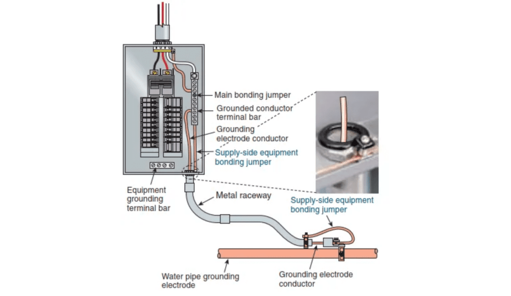
- Grounding Electrode Conductor: A conductor used to connect the system grounded conductor or the equipment to a grounding electrode or to a point on the grounding electrode system.
In simpler terms, the grounding electrode is a conductive object that forms a bridge between the electrical system and the earth. The GEC serves to link this electrode to the electrical apparatus and/or the grounded conductor (neutral).
Types of Grounding Electrodes
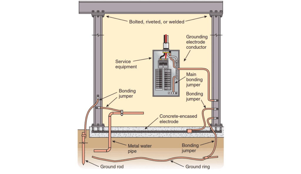
NEC 250.52(A) details several recognized grounding electrode types. When any of the following electrodes are present within a building or structure, NEC 250.50 mandates their interconnection to create a unified grounding system:
Grounding Electrode Types
- Metal underground water pipes
- In-ground support structures made of metal
- Concrete-encased electrodes
- Ground rings
- Rods, pipe, and plate electrodes
- Officially listed electrodes
- Other local underground metal systems or structures
Grounding Electrode Installation Requirements
NEC 250.53 outlines the installation criteria for different grounding electrodes. Some key stipulations include:
- Rod, Pipe, and Plate Electrodes should be:
- Situated beneath the moisture level, devoid of any coatings like paint or epoxy.
- Accompanied by an additional electrode type as detailed in NEC 250.52(A). In most cases, achieving a resistance to earth below 25 ohms is necessary. You can connect this supplemental electrode in various ways, as the NEC lists.
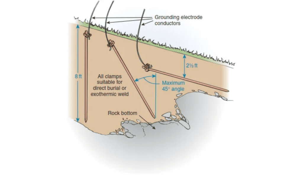
- Installation Depth and Protection: You must ensure that rod or pipe electrodes have a minimum of eight feet of contact with the soil and protect them against physical damage.
- You may drive rod or pipe electrodes at a 45-degree angle when encountering rock bottom. You can also bury it in a trench at least 30 inches deep when encountering rock bottom at a 45-degree angle. The upper end of the electrode must remain flush with or below ground level, unless there is protection against physical damage for both the aboveground end and the attachment of the grounding electrode conductor.
- The rod or pipe electrodes must be a minimum of six feet apart. Rods may only be installed at an angle if it is not possible to drive the rod eight feet vertically. Burying the rod horizontally 30 inches below grade is only permitted if driving the rods vertically or at angle is not possible due to rock bottom.
- Plate Electrodes: These should be installed no less than 30 inches beneath the earth’s surface.
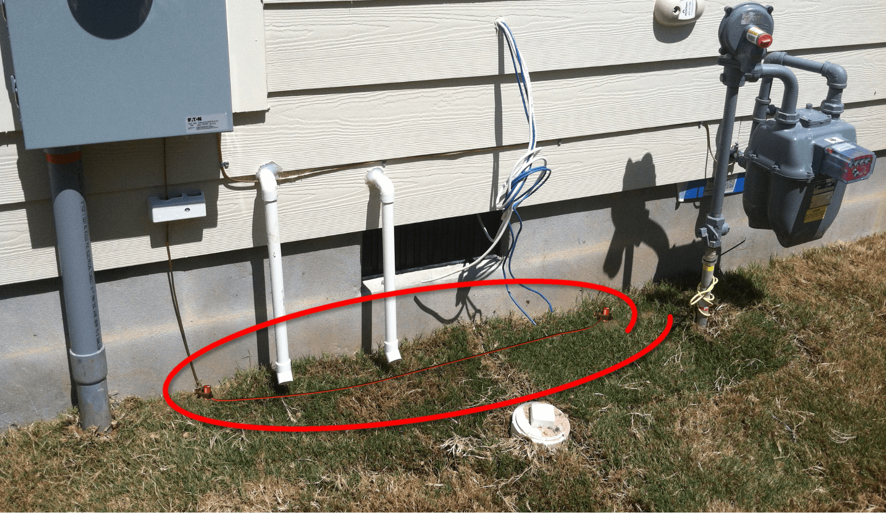
The key point to remember from this section is that, in many instances, you must install at least two ground rods, pipes, or plates unless you can measure or verify a resistance of 25 ohms or less. Measuring soil resistivity can pose challenges and tedium, making it advisable to install an additional ground electrode. Additionally, keep in mind that you can bond the additional grounding electrode in various ways, as mentioned. Most commonly, people bond the electrodes together with a bonding jumper for ease of installation.
Sizing GEC’s
Determining the Correct Size for GEC’s
To size GEC’s correctly, refer to NEC Table 250.66. This involves knowing the size of the largest ungrounded (hot) conductor which feeds the service. For example, if we have a service fed by 2/0 Copper conductors we would need to use a 4AWG Copper or 2AWG Aluminum GEC.
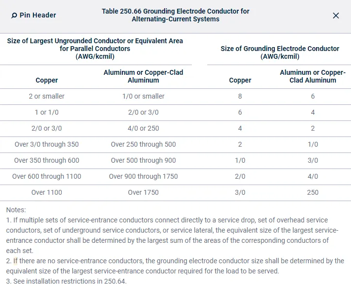
Note 1 mentions the proper way to size GEC’s for multiple sets. The way this is done is by taking the sum of the equivalent area of one phase/line conductor in each set. For example, if we had five sets of three 500kcmil copper conductors, we would add up the area of one conductor of each set. 5 x 500kcmil = 2000kcmil. We would use a 3/0 Copper GEC in this instance.
Raceways and Enclosures Used for GEC’s
NEC 250.64(E) requires that all ferrous metal raceways and enclosures used for GEC’s shall be electrically continuous from the point of attachment and be bonded at each end of the raceway or enclosure to the grounding electrode or GEC. This rule does not apply to nonferrous metal raceways and enclosures.
Closing Remarks
Understanding the grounding electrode and its conductors is pivotal in safeguarding electrical systems and ensuring their optimal functionality. Adhering to the regulations and guidelines set by the NEC not only facilitates the proper setup of these components but also guarantees a safer and more efficient electrical environment. It is our hope that this guide has shed light on the intricacies of grounding electrodes and their conductors, steering you toward a more informed application of these elements in your electrical systems. Check out the “Why Bonding Neutral to Ground is so Important” article next!
All references to the National Electrical Code, NEC, or NFPA are copyrights of the NFPA, these citations are owned by the National Fire Protection Agency and are only here for educational reference.