How To Test Resistance With a Multimeter
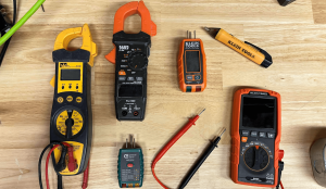
Multimeters are tools electricians use for measuring various electrical parameters, including voltage, current, capacitance, and resistance. Among these measurements, resistance plays a critical role in electronics and appliances. In this article, we will explore the fundamental principles behind how multimeters measure resistance, the different methods used, and the significance of accurate resistance measurements in practical applications.
Understanding Resistance
Resistance is a fundamental property of an electrical component or material that opposes the flow of electrical current. The symbol “R” represents resistance and we measure this in ohms (Ω). Ohm’s law is how we calculate resistance. Which states that the resistance (R) is equal to the voltage (E) across a component divided by the current (I) flowing through it:
When considering electrical theory, we often think about “how electricity works” in terms of voltage and current. But many fail to understand the role of the resistor. When we apply voltage (electrical pressure) across a resistance (a load), a certain amount of current will flow through the circuit. If we change the voltage, or the resistance, more or less current will flow as a result. In addition, a change in resistance affects the electrical power dissipated as heat. For instance, a 100W light bulb transfers 100 joules of energy from the electrical filament per second, in the form of heat and light. In the context of the filament, which is where the light is produced, a significant portion of the energy is dissipated as heat due to the resistance of the filament. If we were to change the filament to have less resistance, more current would flow through it. Which results in more energy dissipated at a higher rate (increasing the wattage, or joules of energy transferred per second).

The Working Principle of Resistance Measurement in Multimeters
Depending on their type (analog or digital) and the resistance range, multimeters use various techniques to measure resistance. However, the basic principle remains the same across most multimeters.
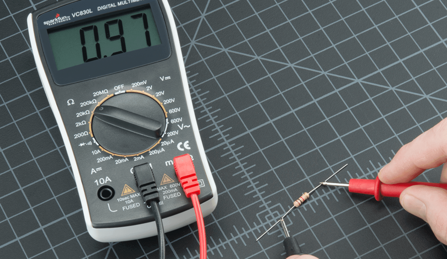
Multimeters test resistance by applying a small, precise voltage to the circuit and measuring the resulting current flow. When measuring resistance, a small known current, usually in the microampere (µA) range, passes from the tester’s battery through the component under test. When the probes are placed across the component or section of the circuit being tested, the multimeter measures the current that flows through the component due to this applied voltage, and any voltage drop which occurs from the resistance. By knowing both the applied voltage and the measured current, the multimeter’s internal circuitry calculates the resistance and displays it on the screen. For digital multimeters (DMMs), the internal circuitry has a resistance-to-voltage converter that changes the measured resistance value into a voltage. Which the screen then displays.
Multimeters typically have a range of settings to accommodate different levels of resistance. Usually from a few ohms to several megaohms (MΩ). Users can manually select the appropriate range for their measurement. In the case of an auto-ranging multimeter, the device will automatically determine the correct range to provide an accurate reading. It is important to note, the range of values the meter can read must correspond to the range of values of the component being tested. Otherwise the values displayed will be incorrect. For instance, a standard electrical tester may only test up to 1000Ω, whereas a special tester known as a megohmmeter may be required to test 100,000Ω components. Testing a 10,000Ω resistor on a meter that maxes out at 1000Ω will result in an overload indication or an “out of range” error. This occurs because the multimeter cannot accurately measure resistance values beyond its maximum range. Leading to either no reading or an inaccurate reading.

Auto-ranging vs. Manual-ranging for Resistance Measurement
Most modern digital multimeters are auto-ranging, which means they can automatically select the appropriate measurement range for resistance based on the component under test, within a certain range. Just as many different multimeters have different ranges of voltages and currents they can handle, they also have gradations in resistance values they can measure. Regardless, the auto-ranging feature makes resistance measurements more user-friendly, especially for beginners or when working with unknown resistance values.
On the other hand, manual-ranging multimeters require the user to select the appropriate range manually. While this may require more effort and knowledge, manual-ranging can be advantageous when working with specific resistance ranges. It allows the user to avoid auto-ranging errors and obtain more stable readings.

Factors Affecting Resistance Measurement Accuracy
Several factors can influence the accuracy of resistance measurements in multimeters:
- Test Lead Resistance: Test leads can introduce errors in the measurement. The longer the test leads and the higher the resistance, the more significant the measurement error.
- Damaged Leads: Often testers get thrown around in tool boxes or left out in the rain. This can be a problem as the leads of the tester are often the most important part to keep in good order. Damaged leads can give unreliable results, especially if the lead is able to separate from the conductor terminated inside of the lead. Ensuring the tester works properly before relying on its measurements is extremely important, no matter what setting you’re testing for.
- Temperature Effects: Some resistors are temperature-sensitive, meaning their resistance value can change with temperature. This effect is more noticeable in high-precision or low-resistance measurements.
- Contact Resistance: The quality of contact between the test leads and the component under test can affect the measurement accuracy. Ensure clean and tight connections to minimize contact resistance.
- Self-Heating: Passing current through the resistor during measurement can generate heat, changing the resistor’s resistance value. This self-heating effect is typically negligible for most resistors, but it should be considered for highly precise measurements.
Conclusion
Multimeters provide a valuable and efficient means of measuring resistance in electrical circuits. By understanding the working principles behind resistance measurement and the different methods used, users can make accurate resistance measurements for a wide range of applications. Accurate resistance measurements are essential for circuit analysis, component testing, quality control, and various other electronic applications. Making multimeters an indispensable tool for engineers, electricians, and electronics enthusiasts alike. Interested in testing for voltage with a multimeter? Check out the “How to test for voltage using a multimeter” article next!