The Optional Method for determining the dwelling unit service load, as specified in Part IV of Article 220 of the 2023 NFPA 70, offers a simplified yet efficient approach compared to the Standard Method. This method is particularly useful for single dwelling units. Whether in separate buildings or within multifamily dwellings, served by a single set of 120/240-volt or 208Y/120-volt 3-wire service or feeder conductors with an ampacity of 100 or greater.

Steps of the Optional Method
Under Article 220.82, the total connected load for a dwelling unit is calculated by adding the loads specified in sections 220.82(B) and (C). Additionally, the neutral load can be determined by 220.61.
- The first step in using the Optional Method involves estimating the general lighting and general-use receptacle loads. Just like the Standard Method, we achieve this by multiplying the unit’s total square footage by a standard rate of no less than 3VA per square foot. (excluding open porches, garages, and unused or unfinished spaces not adaptable for future use). (See 220.82(B)(1)).
- After that we figure in our 3 required circuits required by 220.52: one 20-ampere laundry circuit, and two 20-ampere small appliance branch circuits; each at 1500VA.
- Where we differ from the standard method is that we continue adding appliances and motors before doing our demand factor. With the standard method we only take the lighting, small-appliances, and receptacles; then add the demand factor from Table 220.45. After that we would start adding appliances separately. With the optional method we put all of it together, then add a different demand factor. So we continue on with appliances:
- Take the nameplate rating of all fastened-in-place, permanently connected appliances or those located on specific circuits, including ranges, wall-mounted ovens, counter-mounted cooking units, clothes dryers not connected to the laundry branch circuit, and water heaters.
- Lastly we figure in the nameplate ampere or kVA rating of all permanently connected motors not included in the above appliance load.
- Now that we have all of these loads, we apply a demand factor to the sum of all of it to get our General Demand Load. (220.82(B))
- After we have the general demand load we add in only the largest of the following heating and air-conditioning loads:
- (1) Air Conditioning and Cooling
- 100% of the nameplate rating(s).
- (2) Heat Pump without Supplemental Electric Heating
- 100% of the nameplate rating(s).
- (3) Heat Pump with Supplemental Electric Heating
- 100% of the heat pump compressor rating and 65% of the supplemental electric heating. If the heat pump compressor is prevented from operating simultaneously with the supplementary heat, it does not need to be added to the supplementary heat for the total load.
- (4) Electric Space Heating (less than four separately controlled units)
- 65% of the nameplate rating(s).
- (5) Electric Space Heating (four or more separately controlled units)
- 40% of the nameplate rating(s).
- (6) Electric Thermal Storage and Other Heating Systems
- 100% of the nameplate ratings for systems expected to have a continuous load at the full nameplate value. Systems qualifying under this selection are not calculated under any other selection in 220.82(C).
- (1) Air Conditioning and Cooling
- Then we combine the general demand load and heating and air-conditioning loads to get our Total Demand Load for the dwelling unit.
- Once we get the total demand load we divide that number (in VA) by the voltage of the service (Usually 240V for residential dwellings) which yields the total Amperes for the service.
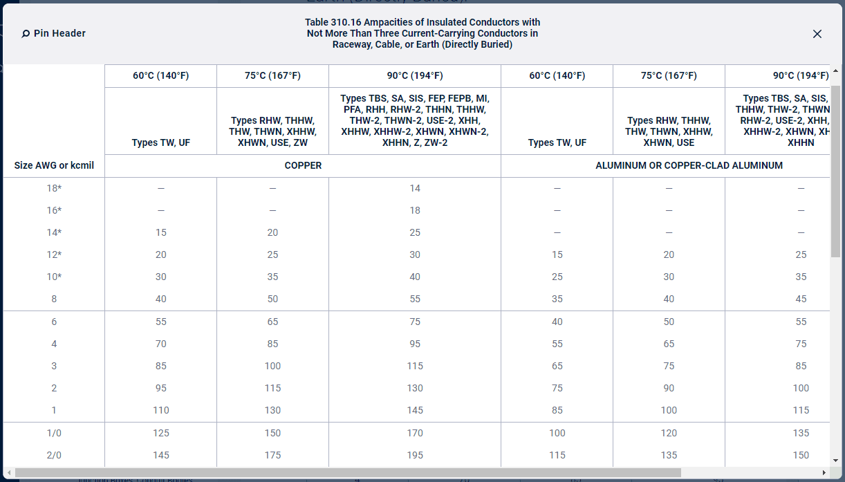
- Now that we have Amperes to work with, we can size our service conductors. We do this using either Table 310.12 or Table 310.16, and if desired, sizing a reduced neutral conductor per 220.61. Per 310.12, if a dwelling has a single-phase 100-400 service, the conductors feeding that service are allowed to be only 83% of the size of the service rating (rating of the service equipment – not the calculated load of the service). If no adjustment or correction factors are required, Table 310.12(A) shall be permitted to be applied rather than using Table 310.16. However, for some, it is preferable to just use Table 310.16 to size these conductors manually. (Note that Table 310.12(A) and Table 310.16 may result in different conductor sizes as a result.)
A Practical Example
To better illustrate this method, let’s consider a dwelling unit encompassing 1,500 square feet with specified circuits and appliances. We’ll also assume this is to be a single-phase 240V service.
- Floor Area: 1,500 square feet
- Small-Appliance Branch Circuits: 2
- Laundry Branch Circuit: 1
- Appliances: Range (12,000 VA), Water Heater (4,000 VA), Clothes Dryer (5,000 VA)
- Heating and Cooling: Electric Space Heating (6,000 VA), Air Conditioning (5,000 VA)
Step 1: Calculate General Loads
- General Lighting and Receptacles: 1,500 sq ft × 3 VA/sq ft = 4,500 VA
- Small-Appliance Branch Circuits: 2 × 1,500 VA = 3,000 VA
- Laundry Branch Circuit: 1 × 1,500 VA = 1,500 VA
Total General Load: 4,500 VA + 3,000 VA + 1,500 VA = 9,000 VA
Step 2: Calculate Appliance Loads
- Range: 12,000 VA
- Water Heater: 4,000 VA
- Clothes Dryer: 5,000 VA
Total Appliance Load: 12,000 VA + 4,000 VA + 5,000 VA = 21,000
Step 3: Apply Demand Factor
Per 220.82(B) we add the general loads and appliance loads together and apply the first 10,000 VA at 100%, and the remainder at 40%. This means:
9,000 VA + 21,000 VA = 30,000 VA
30,000 VA – 10,000 VA = 20,000 VA remaining
20,000VA x 0.4 =8,000 VA
Add the 100% and the 40%: 10,000 VA + 8,000 VA = 18,000 VA
Step 3: Calculate Heating and Air-Conditioning Load
Now that we’ve applied our demand factor we simply need to add the largest load from the heating and cooling options:
- Electric Space Heating: 6,000 VA
- Air Conditioning: 5,000 VA
The largest load is the Electric Space Heating: 6,000 VA
Per 220.82(C)(5) we only use 65% of the nameplate rating of the electric space heating equipment if there are less than 4 separately controlled units. Therefore: 6,000 VA x 0.65 = 3,900 VA
Step 4: Aggregate Loads
Total Calculated Load: 18,000 VA(General Demand Load) + 3,900 VA(Heating) = 21,900 VA
Step 5: Determine Service Size
Divide the total calculated load by the voltage (240V): 21,900 VA / 240 V = 91.25 Amperes
Step 6: Sizing the Service Conductors
According to 230.79(C) single-family dwellings are required to have a minimum service disconnecting means of 100 A, so this will need to be, at minimum, a 100 A electrical service.
Using Table 310.12(A), for a 100A service, the conductors can be 4AWG Copper. However, when we compare this to Table 310.16 we see 4AWG at 75°C is rated for 85A, not 100A as Table 310.12(A) lists it. This is because Table 310.12(A) is applying the 83% rule mentioned in 310.12.
100A x 83% = 83A
As long as we use a conductor that is rated no less than 83A for our 91.25A load, installed on a 100A service, we’re within an allowable range, per 310.12. So rather than installing 3AWG, we can install 4AWG to save money.
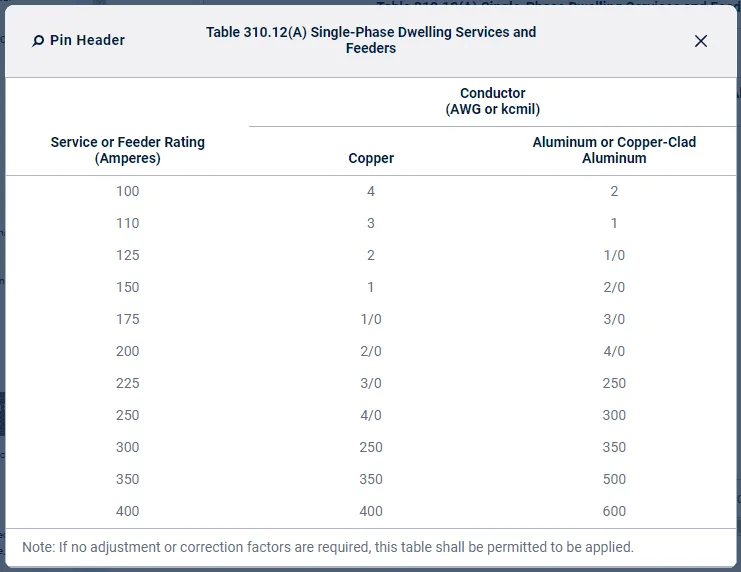
If preferred, rather than using Table 310.12(A) to size the conductors we could use Table 310.16. But this would result in a larger 3AWG 75°C conductor to be used as it does not account for the 83% rule allowed in 310.12. There is nothing wrong with doing this, it will just result in a more expensive install to achieve the same result.
Conclusion
The Optional Method outlined in Part IV of Article 220 in the 2023 NFPA 70 offers a streamlined method of calculating the service load for dwelling units. Taking into account general lighting, appliance loads, and the largest heating or cooling load. This method simplifies the process while ensuring the service and feeder conductors are adequately sized. Promoting both safety and efficiency in electrical installations.
Understanding both the Standard and Optional Methods equips electricians with the necessary tools to tackle a variety of dwelling unit service load calculations effectively. If you’re interested in seeing an example like this for the Part III Standard Method instead, we’ve written an article here which you can read as well.
All references to the National Electrical Code, NEC, or NFPA are copyrights of the NFPA, these citations are owned by the National Fire Protection Agency and are only here for educational reference.


One thought on "Dwelling Unit Service Load Calculations – Optional Method"
Excellent Article
Comments are closed.