Electrical Harmonics in AC Systems
In alternating current (AC) systems, the ideal scenario is one where the electrical waveform is a pure sine wave. However, in real-world applications, this is rarely the case. Deviations from the ideal sine wave, known as harmonics, can significantly impact the performance and efficiency of electrical systems. This article provides an introduction to harmonics, their causes, effects, and how they are managed in electrical systems. Additionally, we will discuss harmonic distortion and its impact on power quality.
What Are Harmonics?
Harmonics in electrical systems are voltage or current waveforms that are integer multiples of the fundamental frequency. If the fundamental frequency of the AC power supply is 60 Hz, the second harmonic would be 120 Hz, the third harmonic 180 Hz, and so on. These harmonic frequencies superimpose on the fundamental frequency, causing distortion in the waveform.
Harmonic Series
- Fundamental Frequency (1st Harmonic): The original sine wave frequency, such as 60 Hz.
- 2nd Harmonic: Twice the fundamental frequency (e.g., 120 Hz on a 60 Hz system).
- 3rd Harmonic: Three times the fundamental frequency (e.g., 180 Hz on a 60 Hz system).
- Nth Harmonic: N times the fundamental frequency.
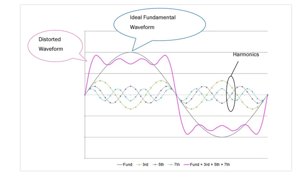
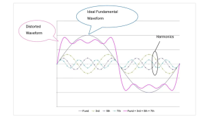
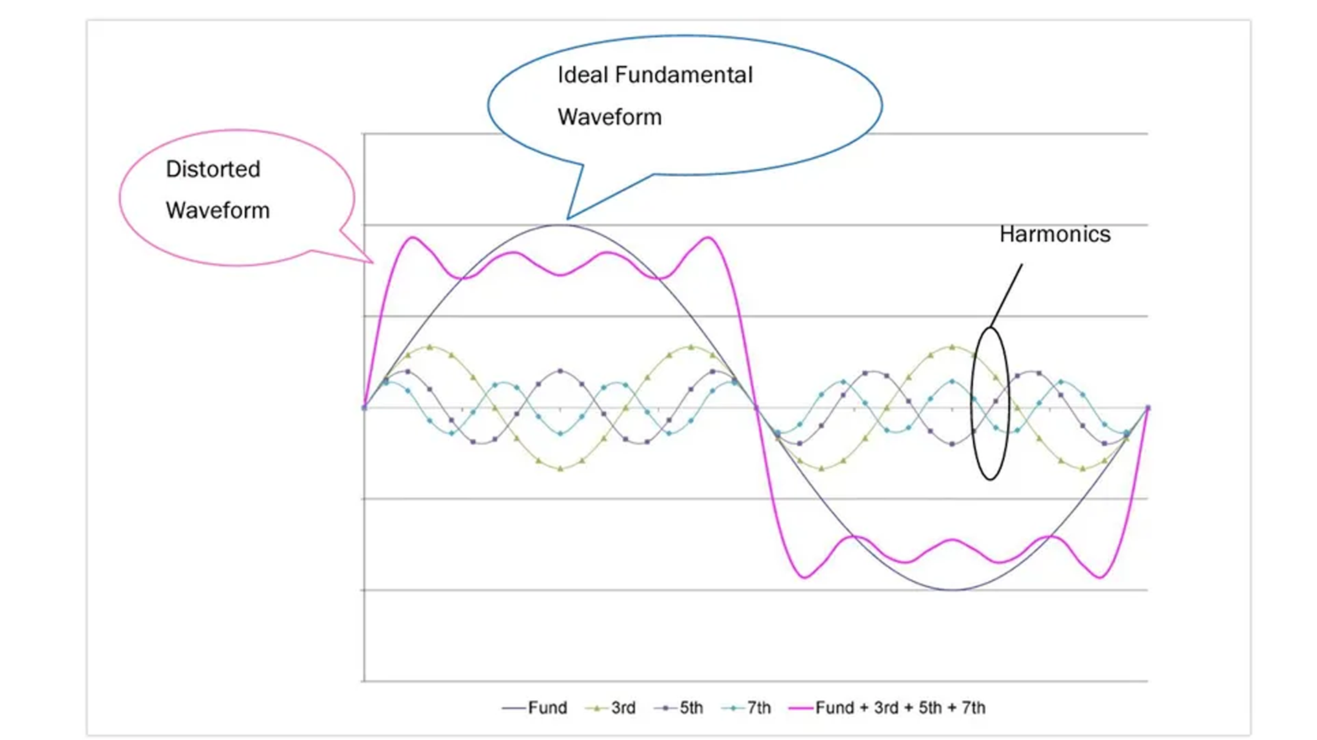
Now if we imagine the pink line above represents a current waveform, rather than a voltage waveform, we can picture an electron moving along the pink line. With a pure sinusoidal wave form the charged particle would simply oscillate up and down along the ideal fundamental waveform (black line). However, due to the effects of multiple harmonics the charge will move abruptly up, then back and forth slightly before oscillating back down where it moves back and forth slightly before returning back to where it started. Understanding that all charges in the conductor are doing this, we can see that rather than normal smooth current flow in the conductor, we now have a rather erratic motion of current, due to the overall harmonic distortion.
Causes of Electrical Harmonics
Harmonics are primarily caused by non-linear loads, which draw current in abrupt pulses rather than a smooth sinusoidal manner. Where charged particles normally oscillate back and forth in a conductor in sinusoidal AC, non-sinusoidal current flow looks jerky and somewhat sporadic. These non-linear loads include a variety of modern electrical devices and systems.
Common Sources of Harmonics
- Electronic Devices: Computers, televisions, and other consumer electronics that use switch-mode power supplies.
- Variable Frequency Drives (VFDs): Used to control the speed of motors, VFDs are significant sources of harmonic distortion.
- Uninterruptible Power Supplies (UPS): Essential for providing backup power, UPS systems often contribute to harmonics.
- Lighting: Fluorescent lights and LED lights with electronic ballasts or drivers.
- Industrial Equipment: Arc furnaces, welding machines, and other industrial machinery.
Effects of Harmonics
Harmonics can have various detrimental effects on electrical systems and equipment. Understanding these effects is crucial for maintaining system performance and reliability.
Equipment Overheating
Harmonics increase the RMS (root mean square) value of the current flowing through conductors, which can cause excessive heating. Harmonic currents add to the fundamental current, resulting in a higher total RMS current. For example, if a system has a fundamental current of 100 A and harmonic currents contribute an additional 5 A, the total RMS current becomes approximately 105 A. This increase in RMS current leads to higher power losses in the form of heat within conductors. This overheating can affect:
- Transformers: Increased core losses and stray losses can lead to overheating and reduced lifespan.
- Motors: Harmonic currents can cause additional heating in motor windings, leading to premature failure.
- Cables: Higher RMS currents can overheat cables, potentially causing insulation damage.
Voltage Distortion
Harmonics can distort the voltage waveform, leading to poor power quality. Non-linear loads draw non-sinusoidal currents, which interact with the system’s impedance, causing voltage drops that deviate from the fundamental sinusoidal shape. This interaction results in voltage waveform distortion, introducing harmonics into the system. The distorted voltage waveform can adversely affect sensitive equipment, leading to malfunctions. This distortion can result in:
- Malfunction of Sensitive Equipment: Devices such as computers, medical equipment, and precision instruments may malfunction or fail due to distorted voltage.
- Interference with Communication Lines: Harmonics can cause electromagnetic interference (EMI), affecting nearby communication lines and equipment.
Reduced Efficiency
Harmonic distortion can reduce the efficiency of electrical systems by causing additional losses in conductors and equipment. This inefficiency translates to higher operational costs and increased energy consumption.
Resonance
In some cases, harmonics can cause resonance in electrical systems. Resonance occurs when the frequency of the harmonic matches the natural frequency of the system’s inductive and capacitive components, leading to amplified voltages and currents. This can result in equipment overheating, insulation failure, or operational disruptions.
Managing Harmonics
Effective management of harmonics is essential to maintain power quality and ensure the reliable operation of electrical systems. Several strategies and technologies are used to mitigate the impact of harmonics.
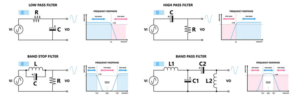
Passive Filters
Passive filters are designed to block or shunt specific harmonic frequencies. These filters consist of inductors, capacitors, and resistors arranged to target the problematic harmonics.
- Single-Tuned Filters: Designed to filter out a specific harmonic frequency.
- High-Pass Filters: Allow high-frequency harmonics to pass through while blocking lower frequencies.
- Band-Pass Filters: Target a specific range of harmonic frequencies.
Active Filters
Active filters use power electronics to inject currents that cancel out the harmonics. These filters are more flexible and can adapt to changing harmonic conditions in real-time.
- Shunt Active Filters: Connected in parallel with the load, injecting compensating currents to counteract harmonics.
- Series Active Filters: Connected in series with the load, modifying the voltage waveform to reduce harmonics.
Harmonic Mitigating Transformers (HMTs)
Harmonic mitigating transformers are specially designed to reduce the propagation of harmonics in electrical systems. They use multiple windings and configurations to cancel out specific harmonics.
Power Factor Correction (PFC)
Improving the power factor can also help reduce harmonics. Power factor correction devices, such as capacitors and synchronous condensers, improve the overall power quality and reduce the impact of harmonics.
Harmonic Distortion and Power Quality
Total Harmonic Distortion (THD)
Total Harmonic Distortion (THD) is a measure of the harmonic distortion present in a voltage or current waveform. It is expressed as a percentage of the fundamental frequency and can be calculated by:
![{"font":{"family":"Arial","size":11,"color":"#000000"},"backgroundColor":"#ffffff","backgroundColorModified":false,"aid":null,"code":"$$THD=\\frac{{\\sqrt[]{V_{2}^{2}+V_{3}^{2}+V_{4}^{2}+...}}}{V_{1}}\\times100\\%$$","id":"11","type":"$$","ts":1733318079556,"cs":"cB0Oi8+TDv4XJjjLCxx66A==","size":{"width":289,"height":52}}](https://lh7-rt.googleusercontent.com/docsz/AD_4nXduVeTeczuVttn7DGvUQTYqo2nrGqx9RKyI2Myu_DqwN4GkV86jHL9hFBMlvKSHFYVfU6rAB69A-GTwUGpMrk7j-c98yxUofdAem32lVK0NRtyWAzech5z5OlRuJDuoUtGMJ6T49A?key=wThBcOX76t1PYu9TZITCTa1j)
Where V1 is the RMS voltage of the fundamental frequency, V2 is the voltage of the 2nd harmonic, V3 is the 3rd harmonic, etc.
To illustrate the calculation of Total Harmonic Distortion (THD) in a 60 Hz electrical system, consider a scenario where the fundamental frequency (60 Hz) has an RMS voltage (V1V_1V1) of 120 V, and the following harmonic components are present:
- 2nd harmonic (120 Hz): V2=2V
- 3rd harmonic (180 Hz): V3=1.5V
- 4th harmonic (240 Hz): V4=1V
![{"type":"$$","backgroundColorModified":false,"aid":null,"font":{"color":"#000000","family":"Arial","size":11},"id":"11-1","code":"$$THD=\\frac{{\\sqrt[]{\\left(2V\\right)^{2}+\\left(1.5V\\right)^{2}+\\left(1V\\right)^{2}}}}{120V}\\times100\\%$$","backgroundColor":"#ffffff","ts":1733320590552,"cs":"2sZRIL5LpB8y2kIQQYAoIg==","size":{"width":332,"height":50}}](https://lh7-rt.googleusercontent.com/docsz/AD_4nXebjpvEjeBRAzZahKW05ieMB_6ypGF1ww5VMKz6i3WQSC5fONEkk0nBmoLsVXfRxcN6pR2kS8f6GhN0UGqDgXNt3RB4Sls4F2bKkkAjDKRpt5YfGCyoWhp7Uvyxu9I1QyVhjJqUPg?key=wThBcOX76t1PYu9TZITCTa1j)
![{"aid":null,"backgroundColorModified":false,"backgroundColor":"#ffffff","id":"12","type":"$$","code":"$$THD=\\frac{{\\sqrt[]{4+2.25+1}}}{120V}\\approx\\,\\frac{2.69V}{120V}\\times100\\%\\approx2.24\\%$$","font":{"size":11,"color":"#000000","family":"Arial"},"ts":1733320728460,"cs":"WbAhPEbkuwKBb0qdQKh/ew==","size":{"width":380,"height":38}}](https://lh7-rt.googleusercontent.com/docsz/AD_4nXf7gUmwGKkgU389Bn2GrzsuJcPSnQBK6JjAHW4Pfcc6MxiCn9MSvOaGNdT0xkl6SgOmbqOoGgDYNiKaMw0xgzjhdTWDhRjwFeIhiez3-4jRKfPrMm7dNs_96fzy6yXSrjZYawaM5Q?key=wThBcOX76t1PYu9TZITCTa1j)
Therefore, the Total Harmonic Distortion in this example is approximately 2.24%. This indicates that the harmonic components constitute about 2.24% of the fundamental voltage, reflecting the extent of waveform distortion in the system. This calculation provides insight into the purity of the waveform by comparing the power of all harmonic components to that of the fundamental frequency. High THD values indicate significant harmonic distortion, which can affect power quality and equipment performance.
Power Quality Standards
Several standards and guidelines have been established to manage harmonic distortion and maintain power quality.
- IEEE 519: Provides guidelines for harmonic control in electrical power systems.
- IEC 61000: Addresses electromagnetic compatibility (EMC) and limits for harmonic emissions.
Compliance with these standards helps ensure the reliability and efficiency of electrical systems.
Conclusion
Harmonics in AC systems are a common phenomenon that can significantly impact power quality and the performance of electrical systems. Understanding the causes and effects of harmonics is crucial for managing them effectively. By implementing strategies such as passive and active filters, harmonic mitigating transformers, and power factor correction, it is possible to mitigate the impact of harmonics and ensure the reliable and efficient operation of electrical systems. Regular monitoring, proper system design, and maintenance are essential for maintaining power quality and preventing harmonic-related issues. As technology and power systems continue to evolve, managing harmonics will remain a critical aspect of ensuring optimal performance and reliability in electrical networks.