Understanding wire sizes is important for electricians. At first it can be confusing to look at a conductor stamped with 4 AWG, another stamped 2/0, and yet another stamped 600 kcmil and know what’s what. The American Wire Gauge (AWG) and circular mils (kcmil) are two key measures used to specify the size of electrical wires. These measurements not only determine how capable a wire is at carrying current, but they also influence the physical and electrical properties of the wire which can affect the entire electrical system’s performance. Here, we delve into the details of AWG and circular mils as outlined in the 2023 NEC, Article 110.6, providing a comprehensive guide on how these measurements are used in practice.
Understanding American Wire Gauge (AWG)
American Wire Gauge (AWG) is a standardized wire gauge system used predominantly in North America to denote the diameter and cross-sectional area of round, solid, nonferrous, electrically conducting wire. The system is inversely related to the diameter and cross-sectional area of the wire; as the gauge number increases, the wire diameter decreases. This relationship means that a 12 AWG wire has a larger diameter than a 20 AWG wire.
The basis of the AWG system lies in the formula for calculating the diameter of the wires. Starting from a gauge of 36, which measures 0.005 inches in diameter, each step on the gauge scale represents a diameter that is 0.890526 times the diameter of the previous gauge. This geometric progression allows for a wide range of sizes, accommodating various applications from delicate electronics to heavy industrial machinery.
In practical terms, AWG is crucial when selecting wire for electrical circuits. It determines the resistance of the wire per unit length, which in turn affects the wire’s capacity to carry current without overheating. For example, lower-gauge (thicker) wires are capable of carrying more current and are used in circuits requiring higher amperage, such as electric ranges and clothes dryers. NEC Table 310.16 provides ampacity ratings for wires of various gauges under different insulation types and temperature conditions, guiding electricians in choosing the correct wire size for safe installations.
Circular Mils Explained
A circular mil is a unit of area used specifically to denote the cross-sectional size of a wire or a cable and is crucial when dealing with larger wire sizes or cables that carry substantial current loads. One circular mil is defined as the area of a circle with a diameter of one mil (one-thousandth of an inch). The formula to calculate the area in circular mils for any given wire diameter is:
Where diameter is in mils.
However, for practical and historical reasons, the direct diameter squared (in mils) is used to define the circular mil area, simplifying calculations and manufacturing specifications.
Circular mils are particularly relevant for wire sizes larger than those covered by the AWG system, typically beyond 4/0 AWG. In these cases, wire sizes are expressed in thousands of circular mils (kcmil or MCM), which provide a direct measure of the cross-sectional area. This measurement is crucial for high-capacity wiring required in utility applications, industrial plants, and large commercial buildings.
NEC and Wire Sizing
NEC Article 110.6 specifies that approved wire sizes must be expressed in AWG or circular mils, ensuring standardization across electrical installations. This standardization helps maintain consistency, safety, and compliance in electrical wiring practices. For every installation, ensuring that the wire gauge or circular mil size matches the demands of the electrical load is critical to preventing wire overheating, voltage drops, and potential electrical fires.
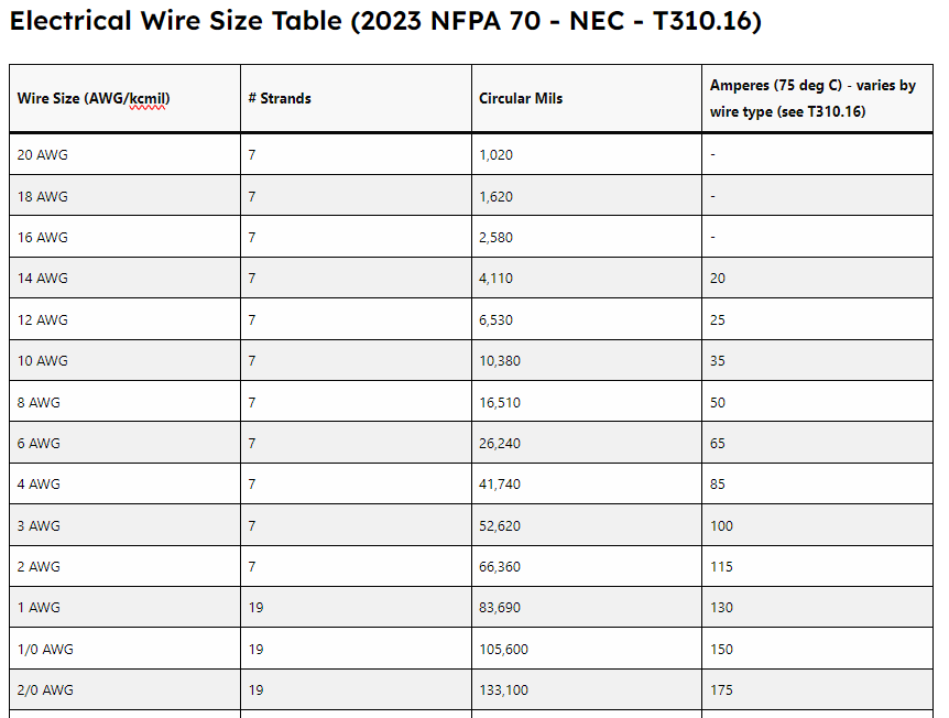
To adhere to NEC requirements, electricians must ensure that the wire size does not only meet the minimum circuit ampacity but also consider factors such as temperature rating, voltage limits, bundling, and environmental conditions. Many of these factors can affect the conductor’s performance. NEC tables such as 310.15, 310.16, and 315.60 provide detailed guidelines on adjusting ampacity for these variables, which must be carefully followed in practice. The following table is an example of standard conductors used in electrical work, their circular mil size, number of strands, and typical current values. Note these current values are not applicable for all conductor insulations. Always consult 2023 NEC Table 310.16 to match specific conductor insulation types with sizes, as well as the derating tables for multiple conductors in a raceway and ambient correction factors from 310.15 before installing any wire in actual buildings.
Electrical Wire Size Table (2023 NFPA 70 – NEC – T310.16)
| Wire Size (AWG/kcmil) | # Strands | Circular Mils | Amperes (75 deg C) – varies by wire type (see T310.16) |
|---|---|---|---|
| 20 AWG | 7 | 1,020 | – |
| 18 AWG | 7 | 1,620 | – |
| 16 AWG | 7 | 2,580 | – |
| 14 AWG | 7 | 4,110 | 20 |
| 12 AWG | 7 | 6,530 | 25 |
| 10 AWG | 7 | 10,380 | 35 |
| 8 AWG | 7 | 16,510 | 50 |
| 6 AWG | 7 | 26,240 | 65 |
| 4 AWG | 7 | 41,740 | 85 |
| 3 AWG | 7 | 52,620 | 100 |
| 2 AWG | 7 | 66,360 | 115 |
| 1 AWG | 19 | 83,690 | 130 |
| 1/0 AWG | 19 | 105,600 | 150 |
| 2/0 AWG | 19 | 133,100 | 175 |
| 3/0 AWG | 19 | 167,800 | 200 |
| 4/0 AWG | 19 | 211,600 | 230 |
| 250 kcmil | 37 | 250,000 | 255 |
| 300 kcmil | 37 | 300,000 | 285 |
| 350 kcmil | 37 | 350,000 | 310 |
| 400 kcmil | 37 | 400,000 | 335 |
| 500 kcmil | 37 | 500,000 | 380 |
| 600 kcmil | 61 | 600,000 | 420 |
| 700 kcmil | 61 | 700,000 | 460 |
| 750 kcmil | 61 | 750,000 | 475 |
| 800 kcmil | 61 | 800,000 | 490 |
| 900 kcmil | 61 | 900,000 | 520 |
| 1000 kcmil | 61 | 1,000,000 | 545 |
Conclusion
Understanding AWG and circular mils is essential for anyone involved in the electrical trades. These measurements provide a foundation for selecting the appropriate wire size, which is crucial for ensuring electrical safety and efficiency. By complying with NEC 110.6 and utilizing the detailed tables and guidelines provided in the NEC, electrical professionals can ensure that they are making informed decisions that comply with the highest safety standards in wire sizing and electrical installation.
All references to the National Electrical Code, NEC, or NFPA are copyrights of the NFPA, these citations are owned by the National Fire Protection Agency and are only here for educational reference.