How Alternating Current Systems Work
Alternating current (AC) is the backbone of modern electrical power systems. It powers our homes, industries, and cities, and is crucial for the efficient transmission of electricity over long distances. This article provides a detailed explanation of how AC works, including its generation, transmission, and typical applications. We will also discuss sine waves, frequency, and phase, which are fundamental concepts in understanding AC.
Generation of Alternating Current
AC is generated by rotating a coil within a magnetic field, a process known as electromagnetic induction. This principle was discovered by Michael Faraday in the early 19th century and is the basis for most electrical power generation today. An AC generator, or alternator, converts mechanical energy into electrical energy. It consists of the following main components:
- Rotor: The rotating part of the generator, which produces a changing magnetic field.
- Stator: The stationary part of the generator that contains coils of wire in which the electric current is induced.
- Prime Mover: The mechanical force that drives the rotor, which can come from various sources such as steam turbines, water turbines, internal combustion engines, or wind turbines.
As a source of energy, such as a waterfall, forces turbines to spin the rotor inside the generator spins, creating a changing magnetic field that induces an alternating current in the stationary stator windings. These stator windings begin producing current which travels through the conductors outward through an external circuit, powering whatever load is hooked up to these conductors. The resulting current alternates direction periodically (60 times per second – 60Hz – in the U.S.), producing the AC waveform.
The Nature of Sine Waves
Understanding Sine Waves
The most common waveform of AC is the sine wave, which is characterized by a smooth, periodic oscillation. Sine waves represent an object oscillating over time, and are often used to represent the motion of a spring, or a vibrating object such as a particle. In electrical circuits, since power is generated by a rotating generator – causing current to vibrate back and forth in alternating current systems. This oscillating back and forth can be represented on a two dimensional graph with respect to time using a sine wave.
Sine waves can be described by the following properties:
- Amplitude (A): The maximum value of the wave, representing the peak voltage or current.
- Frequency (
): The number of cycles the wave completes in one second, measured in hertz (Hz). For example, the standard frequency in most of the world is 50 Hz, while in North America it is 60 Hz.
- Period (T): The time it takes for one complete cycle of the wave. It is the reciprocal of frequency:
- Phase (θ): The position of a point in time on the wave cycle, measured in degrees or radians. Often a waveform can be pushed “out of phase” by certain factors meaning the waveform has slid right or left along the timeline or position in rotational motion.
Mathematical Representation
A sine wave can be mathematically represented on a cartesian plane as:
When plugging this equation into a graphing software or calculator we see the following waveform produced:
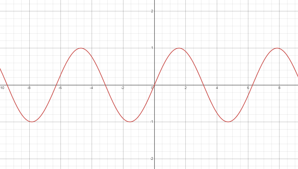
On this graph we can see the x-axis represents time, for example seconds or milliseconds. It could also represent degrees if we’re evaluating rotational motion rather than vibration back and forth. (In AC systems, the rotational motion of a generator over 360 degrees is what causes the oscillation of electrons to occur, so understanding this graph in either terms works equally.
The y-axis in the graph above represents the amplitude of the waveform, and amplitude is defined as the magnitude from zero in either the up or down direction (in most cases this represents voltage positive above the x-axis or negative below the x-axis).
Frequency and Phase
Cycles Per Second (Frequency)
Frequency is a crucial characteristic of AC, determining how quickly the current changes direction. High-frequency AC can carry more data and is used in communication systems, while standard power frequencies (50 Hz or 60 Hz) are used for general power distribution. Frequency can be changed depending on the load, for instance a power supply for a laptop computer may plug into a 60Hz wall receptacle but internally may step the frequency up to hundreds or thousands of hertz to perform a specific function. This simply means the oscillation of these charged particles is being rapidly increased.
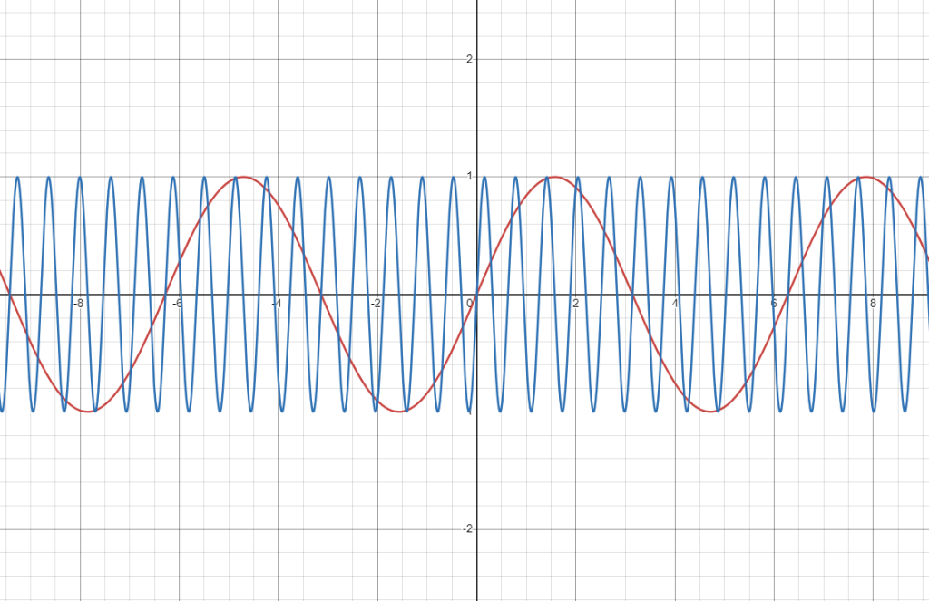
In the image above the red sine wave could represent a slow frequency, such as 60Hz, and the blue sine wave could represent a faster frequency such as 1.2kHz. As we see the vibration back and forth is the only thing which changes – not the amplitude of voltage or current, whichever waveform is being analyzed. That’s not to say the amplitude cannot also change, it’s just to say that in this graph, there is no change in amplitude. So the same circuit, let’s say 120V, remains 120V even though we’ve increased the speed of oscillation by 20x.
Phase
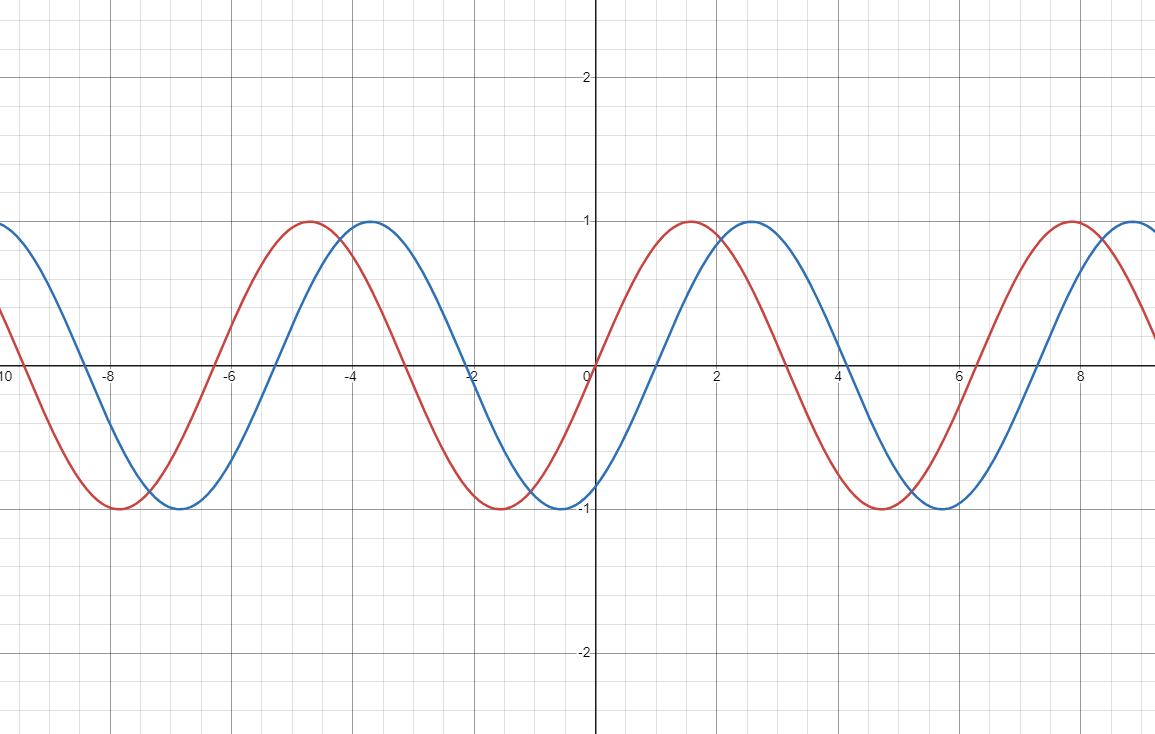
Phase refers to the timing of the waveform relative to a reference point. In alternating current systems, phase differences can occur between multiple waves, leading to constructive or destructive interference. Understanding phase is essential in applications such as power distribution, signal processing, and telecommunications.
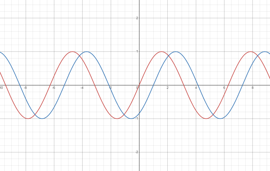
In the image above we see two identical sine waves, but they’re not on top of one another, instead the blue wave is slightly “out of phase” with respect to the red one. This is common in AC circuits, where the voltage waveform (in red) is slightly leading the current waveform (in blue) as a result of reactive components in the circuit. In resistive circuits this does not occur, however in AC circuits there is an added element we must consider when calculating impedance because of inductors and capacitors present in AC circuits.
Transmission of Alternating Current
Advantages of AC for Transmission
Alternating current systems are preferred for transmitting electricity over long distances due to several advantages. The first is being able to convert from one voltage to another. AC voltage can be easily transformed to higher or lower levels using transformers, where DC cannot. High voltages are used for long-distance transmission to reduce energy loss, and then stepped down to safer levels for local distribution. The second is that AC systems are more efficient for power transmission because they can minimize energy losses compared to DC systems.
The Transmission Process
- Generation: Electricity is generated at power plants using AC generators (alternators).
- Step-Up Transformation: The generated voltage is stepped up to high levels (hundreds of thousands of volts) using transformers to reduce energy loss during transmission.
- Transmission and Distribution: The high-voltage AC is transmitted through power lines over long distances to substations where voltage is reduced down to a lower distribution voltage (often between 7kV and 15kV).
- Step-Down Transformation: Near the destination, the voltage is stepped down again using transformers to levels suitable for utilization (e.g., 240V for residential use).
Applications of Alternating Current
Residential and Commercial Power
AC is the standard form of electricity delivered to homes and businesses. It powers lighting, appliances, HVAC systems, and office equipment. The ability to easily transform AC to different voltage levels makes it versatile for various applications.
Industrial Power
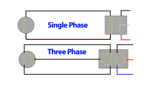
Industries use alternating current systems to power machinery, motors, and other equipment. AC motors are preferred in industrial applications due to their robustness, efficiency, and ease of control. Three-phase AC power is commonly used in industrial settings because it provides a constant power flow and is more efficient for heavy loads.
Transportation
AC is used in transportation systems such as electric trains and trams. These systems often operate on high-voltage AC, which is converted to the appropriate voltage levels using transformers.
Communication and Signal Processing
AC is fundamental in communication systems for transmitting signals over long distances. Modulated AC signals carry information in radio, television, and telephone systems. The frequency and phase of these signals are manipulated to encode data, which can then be decoded by receivers.
Details of AC Waveforms
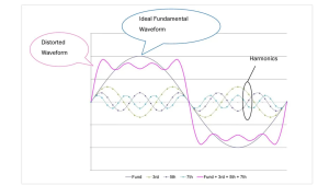
Harmonics
In real-world alternating current systems, waveforms are not always perfect sine waves. Harmonics are higher-frequency components that distort the waveform, resulting from nonlinear loads such as electronic devices and fluorescent lighting. Harmonics can cause inefficiencies and potential damage to equipment if not properly managed.
RMS (Root Mean Square) Values
For AC, the root mean square (RMS) value is used to express the “effective” voltage or current, or more accurately, the equivalent voltage that would produce the same amount of power in a DC circuit with the same voltage. The RMS value of a sine wave is:
This means the RMS voltage will always be less than the Peak voltage. For example, our digital multimeters calculate and display RMS voltage to read 120V, which means that the actual peak voltage the meter is measuring is closer to 170V! So while the meter is measuring a peak voltage of 170V, only 120V is the “effective” voltage, representing the amount that does equivalent useful work as a 120V DC source. This is why our test equipment uses RMS values to display to us, rather than peak values.
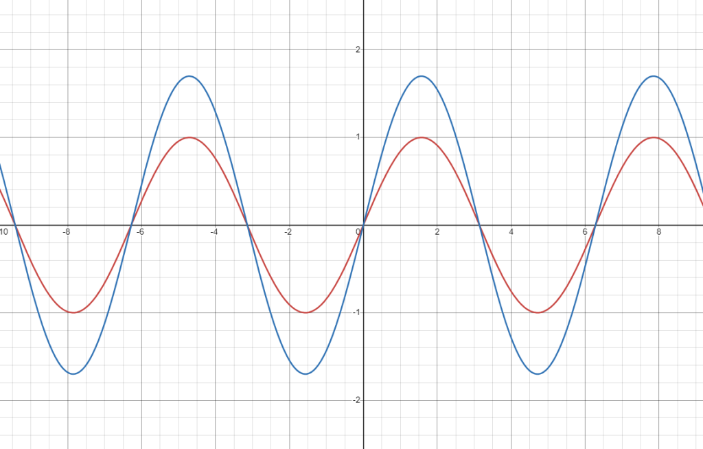
The above image shows an example of peak voltage (blue) and RMS voltage (red). Rearranging our equation we can see that RMS voltage is around 70.7% of peak voltage.
Conclusion
Understanding alternating current (AC) is essential for electricians or anyone working with electrical systems. AC efficiently transmits power over long distances, easily transforms voltage levels, and is used everywhere—from homes to industries. By learning the basics of AC generation and transmission we gain a deeper appreciation for AC’s role in powering our world. Learning about concepts such as phase, frequency, RMS, and sine waves helps us to understand the system on a deeper level, allowing us to better design and troubleshoot electrical systems. Check out “What is Direct Current and How Does it Work?” next!