Written by Mark Delle Bovi
Equipment Grounding Conductor Basics
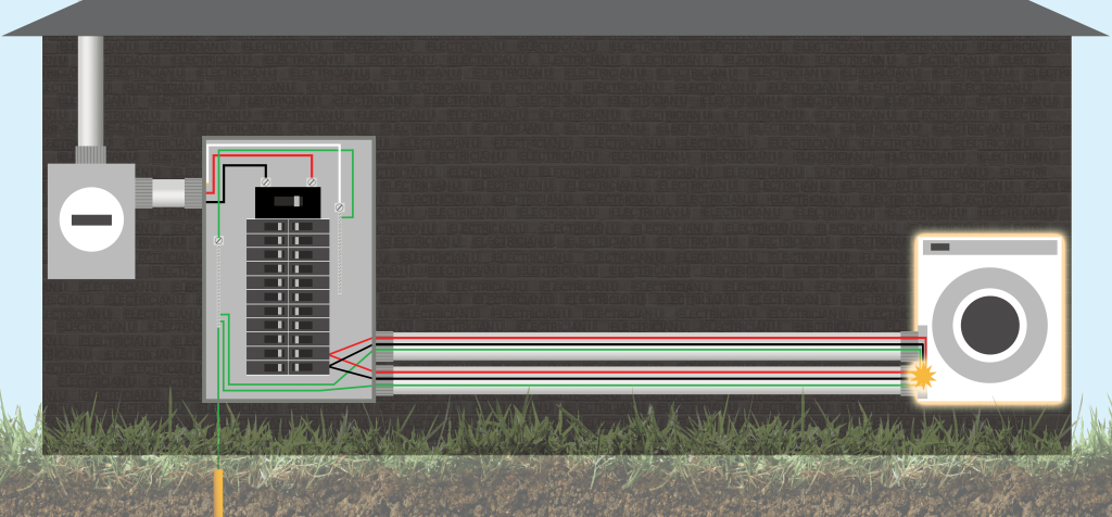
The Equipment Grounding Conductor, or EGC, is an important part of the electrical system. The goal of the EGC is to provide a ground to any metal parts of equipment that do not carry a current that could become energized due to a fault condition. The EGC provides a safe and effective path for ground fault current to flow, with the end result being a breaker tripping to clear the fault. The 2023 National Electrical Code discusses the handling of equipment grounding conductors, and Part VI of Article 250 covers the specifics. It’s one thing to read the rules for installing EGCs, choosing materials, and appropriate methods. However, it’s not often we talk about calculating for voltage drop on this conductor when length becomes an issue. We will break into some voltage drop examples to show how we deal with extremely long feeders, but first let’s discuss sizing and installing EGCs per code.

https://esub.com/
Installation Requirements of the Equipment Grounding Conductor
The equipment grounding conductor can be either an approved metallic conduit/raceway or a dedicated conductor run with the circuit or feeder conductors in the conduit. In this article, we will be discussing the wiring method of utilizing conductors (wires), specifically 250.118 discusses all the requirements when using a raceway as an EGC, as well as the various types permitted.
Sizing of Equipment Grounding Conductor
250.122 mandates that the sizing of equipment grounding conductors depends on the Overcurrent Protection Device (OCPD) protecting the conductors of the circuit. This means, in general, we use the breaker size of a circuit to determine the equipment grounding conductor size.
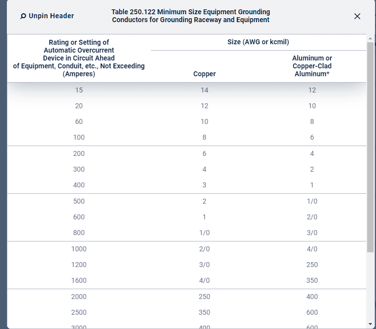
“250.122(A) Size of Equipment Grounding Conductors. Copper, aluminum, or copper-clad aluminum equipment grounding conductors of the wire type shall not be smaller than shown in Table 250.122. The equipment grounding conductor shall not be required to be larger than the circuit conductors supplying the equipment.”
https://link.nfpa.org/
NEC Table 250.122 serves as the reference table for sizing the EGC, providing essential guidelines for proper EGC selection. Match the fuse size or circuit breaker size used to determine the appropriate size of the copper or aluminum EGC.
NEC 250.122 (C): Multiple Circuits
Where a single equipment grounding conductor is run with multiple circuits in the same raceway, cable, or cable tray, it shall be sized for the largest overcurrent device protecting conductors in the raceway, cable, or cable tray. Equipment grounding conductors installed in cable trays shall meet the minimum requirements of 392.10(B)(1)(c).
Therefore, in a single raceway with multiple circuits, size the EGC based on the largest OCPD size.
Voltage Drop Example 1: Let’s say we have a two-inch raceway with a 30 amp circuit, a 60 amp circuit, and a 100 amp circuit. What size EGC would we need?
- Step 1: Find the largest OCPD required in the raceway: 100 amps
- Step 2: Use Table 250.122 to find the EGC based on 100 amps: 8-AWG copper or 6-AWG aluminum
This means we would select an 8-AWG copper equipment grounding conductor to run with all of the circuits in the raceway, and it would protect all of smaller circuits as well as the largest.
Sizing Equipment Grounding Conductors With Parallel Feeds
NEC 250.122(F) covers the requirements for conductors in parallel and equipment grounding conductor requirements.
- NEC 250.122(F)(1)(a) Conductors in parallel but run in the same raceway: a single wire type equipment grounding conductor, sized based on Table 250.122
- NEC 250.122(F)(1)(b) Conductors in parallel but run multiple raceways: a single wire type equipment grounding conductor shall be installed in each raceway sized based on Table 250.122.
Sizing Equipment Grounding Conductors Based on Increase of Conductor Size Due to Voltage Drop
Increasing the conductor length leads to an increase in voltage drop along the conductor. To mitigate the overall voltage drop, one can increase the size of the conductors.
- Per NEC 250.122(B), wire-type equipment grounding conductors shall increase in size proportionately to the increase in circular mil area of each ungrounded conductor.
Voltage Drop Example 2: A 250 amp load is supplied by a 250 amp breaker 500 feet away. The conductors are 250kcmil with a 4-AWG copper EGC. With a conductor size of 500kcmil, what is the appropriate size for the EGC?
METHOD 1 using cross-sectional area:
- Step 1: find the ratio of existing conductors. 500/250 = 2
- Step 2: find the cross-sectional area of 4 AWG EGC from Table 8 in Chapter 9 of NEC: 41,740 cmil
- Step 3: find the cross-sectional area of the new EGC = 41,740 cmil (4-AWG) x 2 = 83,480 cmil
- Step 4: use table 8 in chapter 9 of NEC to find the new GEC size based on 83,480 cmil: 1-AWG
All references to the National Electrical Code, NEC, or NFPA are copyrights of the NFPA, these citations are owned by the National Fire Protection Agency and are only here for educational reference.