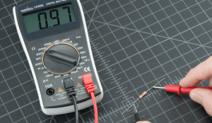
How To Test For Voltage Using a Multimeter
Multimeters are important electrical measurement tools that allow users to measure various values in a circuit. Like voltage, current, resistance, capacitance, and more. Among these measurements, voltage ranks as one of the most commonly measured electrical values. In this article, we will cover the fundamental principles behind how multimeters measure voltage, the different types of voltage measurements, and how to safely test for voltage.
The Working Principle of Multimeters
Before diving into how to use a multimeter to test voltage, let’s briefly understand the working principle of them. Multimeters are more than typical meters. They can measure several different properties of a circuit – hence the word “multi” in the name. Multimeters are based on the concept of ohm’s law in electrical circuits. They use the flow of current to make measurements in circuits where a voltage provides pressure across a resistance, allowing current to flow. They have three main components:
- Voltage: This is the primary setting responsible for measuring electrical potential between two points in a circuit. We call the difference of electrical potential voltage, and it exists in both direct current (DC) and alternating current (AC) circuits.
- Current: This setting measures the flow of electrical current in the circuit by two methods. Either by introducing the meter into the circuit to act as a conductor and measure current flow internally. Or by clamping around a conductor to sense the intensity of expanding and collapsing magnetic field around a conductor.
- Resistance: Multimeters can also measure the resistance of components such as resistors and heating elements. This feature allows users to check to see what a certain heating element’s resistance is, so they can calculate the current flow through the resistor, and know what size conductors will be needed to supply the element. Additionally the continuity setting, often the same setting as resistance, can be used to determine if a conductor loop is broken or not.

Voltage Measurements in Direct Current (DC) Circuits
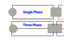
Direct current (DC) is the type of electrical current that flows in one direction, typically provided by batteries and power supplies. Measuring voltage in a DC circuit involves a simple setup within the multimeter.
Inside the multimeter, there is a voltage measuring circuit that consists of a voltage divider network or an analog-to-digital converter (ADC) for digital multimeters. The voltage divider network divides the input voltage by a known ratio. The system then applies the resulting voltage to the ADC, which converts the analog voltage into a digital value.
When the multimeter probes connect to a voltage source, a small current flows through the internal voltage divider network to obtain the voltage value. The multimeter’s display shows the voltage reading in volts (V) with the appropriate decimal places for better accuracy.
Voltage Measurements in Alternating Current (AC) Circuits
Alternating current (AC) flows in both directions, oscillating periodically depending on the frequency of the generator or source. AC voltage measurements can be a bit more complex than DC measurements due to the changing polarity of the voltage.
The digital values we see on the screen of a multimeter are not accurate representations of the true voltage present in the circuit. There are peak voltages, and effective voltages, and what the tester is displaying the vast majority of the time is the effective voltage.

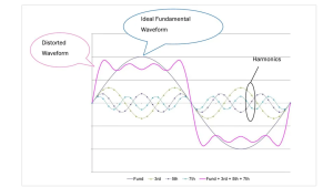
Peak voltage is the maximum voltage value reached in either the positive or negative direction during a complete cycle of an alternating current (AC) waveform. It represents the highest point of the voltage swing but does not provide a complete picture of the power delivered by the waveform.
On the other hand, the effective voltage, also known as the root mean square (RMS) voltage, is a measure of the equivalent DC voltage that would produce the same amount of heat in a resistive load. The RMS value is crucial because it provides a more accurate representation of the power that the AC voltage can deliver to a load. For a pure sinusoidal AC waveform, the RMS voltage is equal to the peak voltage divided by the square root of 2 (approximately 0.707 times the peak voltage).
Say, for example, our multimeter displays 120V, representing the RMS voltage, not the peak voltage. If we want to know the true peak voltage across the conductor we’re measuring, we need to calculate it. We would take the 120V and multiply it by the square root of 2:
We can also do the inverse; if we know our peak voltage and want to figure out the effective RMS value of that peak, we would use the following:
Modern digital multimeters have a built-in RMS converter that processes the AC voltage signal and displays the RMS value directly on the screen. This makes AC voltage measurements as straightforward as DC measurements, and users don’t need to perform any additional calculations.
Common Challenges in Voltage Measurements
While multimeters are highly reliable tools, there are certain challenges that users may encounter when measuring voltage:
Noise and Interference: In some situations, electrical noise and interference can be induced into the meter (or leads). Which affects voltage measurements and leads to inaccurate readings. Shielded cables and proper grounding can help mitigate these issues.
Floating Voltages: In some circuits, voltage levels may appear to “float” or fluctuate. In such cases, using a multimeter with an averaging or smoothing function can provide more stable readings.
Unseated Leads: One thing that happens from time to time with two-piece leads, is that the leads become disconnected internally. This results in taking a measurement on a live circuit, but since the connection to the lead is not seating down properly the meter shows no power present. This is a potentially dangerous situation since the user still sees data on the screen and assumes the circuit is dead. Ensuring the leads are pushed together properly and making a connection is crucial, and testing continuity between the leads before using is a necessity with meters that have detachable two-piece leads.
Battery Issues: Many multimeters read true readings until the battery dies. They will simply shut off until a new battery is installed. However, there are brands/models that will simply begin showing incorrect readings near the end of battery life. It’s extremely important to understand how your meter functions to mitigate bad readings.
Ghost Voltages: Ghost voltages are stray voltages that appear in electrical circuits due to capacitive coupling. This typically happens when no significant current is present. These can lead to misleading readings on a multimeter. Using a low-impedance (LoZ) mode or a voltage tester specifically designed to filter out ghost voltages can help provide more accurate readings.
How to Test For Voltage
Whether you’re using a digital multimeter or a voltage tester with leads, the following steps will guide you through the process safely and accurately.
- Ensure multimeter has good batteries. If the meter does not come on when flipped to a measuring setting, the batteries may be dead
- If meter has removable leads, ensure they are pressed all the way in otherwise voltage may be present even though the meter says there is no voltage.
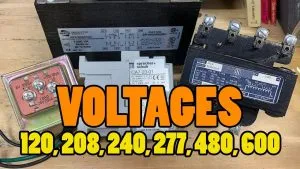
- Be sure the meter is rated for the voltage class you’re testing. For instance a 600V-rated tester should not be used to test 1,000V or the meter can become damaged.
- Wear PPE – allowing yourself to get close to an energized piece of equipment can be deadly if you’re not trained in working with live electrical systems. Always wear eye protection, hand protection, and any other PPE required to work on specific live equipment/environments to avoid getting hurt. If you’re not sure – you don’t have the proper training and shouldn’t be doing this in the first place!
- Flip the meter to the voltage setting, usually noted by a “V” – if using a digital multimeter (DMM) be sure the leads are inserted in the correct spots for reading voltage. Most testers do not require moving leads around, but many benchtop-style DMMS do.
- Touch one lead to one object which is supposed to have voltage present.
- Touch the other lead to another object which may or may not have voltage present.
- While holding the leads firmly on the objects being tested, read the display on the screen.
- Some testers may have a “HOLD” function, allowing the user to press the “HOLD” button to record the reading. This allows the user to walk away and the numbers on screen stay there.
- When finished, remove both leads from both items being touched.
Conclusion
Multimeters are indispensable tools for anyone working with electrical circuits. Understanding how they measure voltage is essential for obtaining accurate and reliable readings. Whether in direct current (DC) or alternating current (AC) circuits, multimeters rely on voltage dividers, analog-to-digital converters, and RMS converters to convert electrical signals into readable measurements. Always prioritize safety and use the appropriate voltage range when making measurements to prevent accidents and ensure accurate results in your electrical projects.