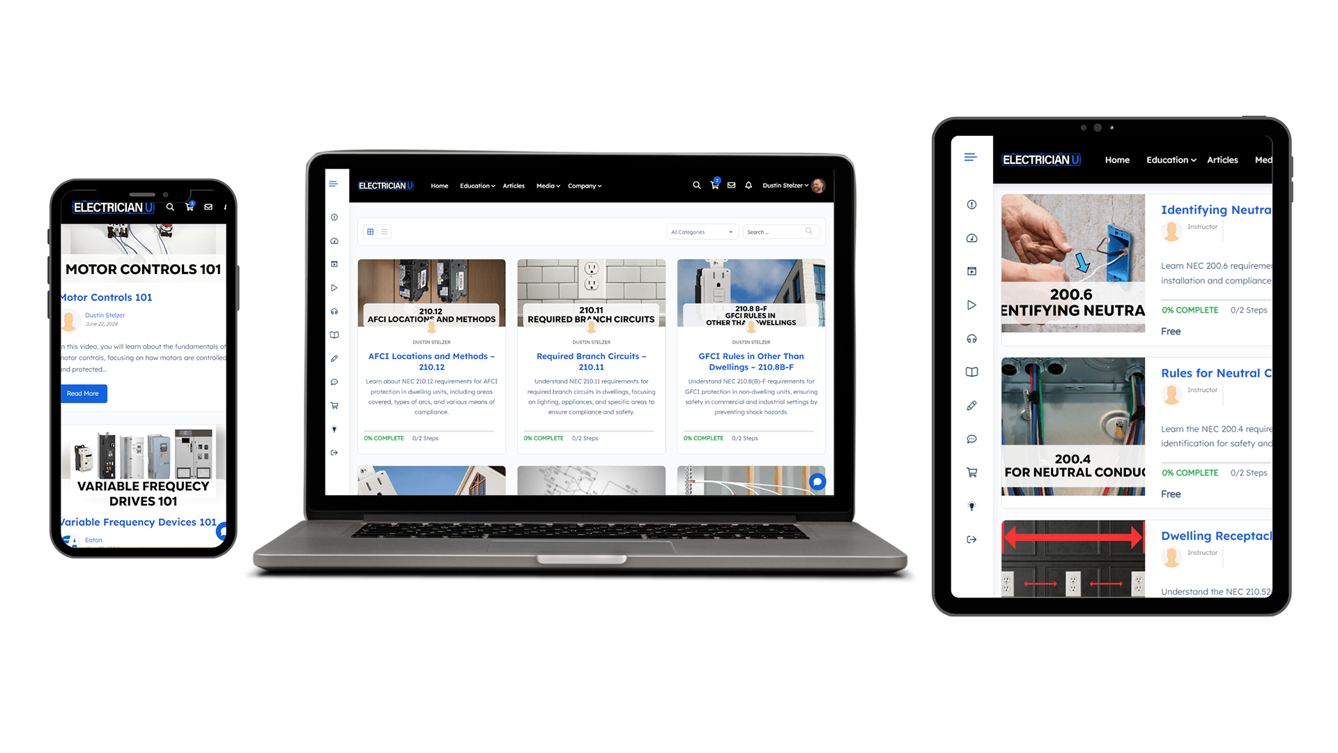
Control Relays – HOW THEY WORK & WHAT THEY’RE FOR

A relay is a type of electromagnetic switch, similar to a contactor, that can be controlled remotely with electricity, rather than needing manual input as a standard switch would.

CONTROL RELAYS

control-relays-ice-cube-120v-coil-10-amp-12v-24v

Relays can be used to control normal loads, as a contactor would, however the benefit of a relay is they come with multiple normally-open (N.O.) and multiple normally-closed (N.C.) contacts – allowing you to use it to power some things on, while removing power from others at the same time.

The reason they are often called “control-relays” is because they’re typically used at lower voltages/lower amperages to control other devices such as contactors which are normally higher voltage and higher current. Many times you’ll find a control relay being controlled by smaller electronic circuits, events, or programs. When an electric signal is sent to engage the coil inside, it can send power to other devices which can turn them on or off – or both simultaneously.

24v-control-relay.png
control-relays.png
 

THE COIL

11-pin-ice-cube-relay.png

On the inside of a relay you’ll find a coil of wire around two pieces of metal. When we send current through that coil of wire, the two pieces of metal suck together through electromagnetism. These pieces of metal that are opening or closing, are the “switch” for the relay to turn on and off.

Coils come in many different voltage ratings. There are many types of coils out there that are controlled at 12-volts, 24, 120, even up to 240. However, the amount of current (amps) that the contacts can handle flowing through them is typically lower – around 5 to 10 amps.


THE CONTACTS

11-pin-and-8-pin-relays.png

There are typically several sets of contacts on every relay. The contacts are the terminations where your incoming and outgoing circuitry is wired. For example, we would normally run a “control circuit” from the panel, to a photocell, then to the coil terminals of the relay. Then we’d run a few circuits from the panel to a different set of contacts on the relay called the “common” terminals. From the relay out to the loads being switched on and off, we’d run the remaining wires – landed on either the normally-open or normally-closed terminals, depending on what we hope to have them do when current is sent to the relay’s coil.

The number of contacts varies widely by the type of relay. For example an 8-pin cube relay has 8 contacts, where an 11-pin cube relay has 11 contacts. On both relays, two of the contacts are taken up by the coil but the 8-pin will have 2 “common” contacts, where the 11-pin has 3. Everything else for both of these relays are just normally-open and normally-closed contacts for you to wire however you need to for your specific application. All of these contacts are on a base that is separate from the mechanical portion of the relay. In the case of the cube relay below, there are pins that stab in to this base which correlate to specific functions inside the relay. Most of the time when a relay goes bad you can pull the cube portion off of the base and change it out for a new cube.

11pin-vs-8pin-ice-cube-relays
 

SUMMARY

Relays are pretty easy to understand once you realize they’re just switches that require electricity to be the thing doing the switching. The hard part to understand for most people is how the normally-open and normally-closed thing works. I’ll be doing another video coming soon that talks about what these terms mean, as well as showing how to wire something in both states to get a grasp on how to wire relays out in the field. But for the time being, just understand that when you see a relay, you’re seeing a switch that is being told to turn on and off by an electrical signal somewhere.

Please check out the Electrician U Facebook page and subscribe to the YouTube Channel if you like these videos! Also check out the Electrician U Instagram page.

**Disclaimer – These videos are for training purposes alone, all work done on electrical systems should be done by a licensed and insured electrical contractor.  If you are not an electrician, do not attempt any of the work you are seeing in these videos.**