Written by Mark Delle Bovi
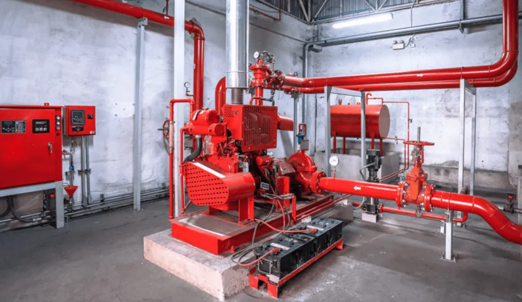
What is a Fire Pump?
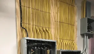
Modern building codes usually mandate the installation of fire protection sprinkler systems throughout new buildings. The primary function of these sprinkler systems is to safeguard the structure from fire damage and prevent the fire from spreading. Therefore, providing a safe evacuation route for the occupants. To ensure optimal performance, the sprinkler system requires a specific pressure level, maintained throughout the system. This is where a fire pump comes into play. Read on, for all the ins and outs of installation.
During the design phase of the fire protection system, engineers often begin with the water pressure of the incoming service. Typically, the sprinkler system has its dedicated water service. Building codes require maintaining a certain pressure level consistently at the furthest point in the system. When the pressure level drops below the mandated standards, the system activates a fire pump. The pump increases the pressure until it reaches the desired point and remains operational indefinitely, ensuring the sprinkler system functions as needed. This continuous operation is crucial to consider when designing the electrical supply for fire pumps.
Source – https://phcppros.com/
Article 695 of the 2023 National Electrical Code (NEC) contains all the essential information regarding the electrical requirements of fire pumps. So, we will primarily focus on two areas of NEC 695: Power Sources, and Continuity of Power. Additionally, we will explore overcurrent protection and conductor sizing, both topics that 695 covers.
Fire Pump Power Sources
NEC 695.3(A) necessitates that individual sources must be reliable and capable of continually supporting the sum of the locked-rotor current of the fire pump motor(s) and pressure maintenance pump motor(s); along with the full-load current of any associated equipment. The authority having jurisdiction or AHJ is responsible for determining the reliability of a single utility power source. To consider it as a power source it must be one of the following, per 695.3(A):
- 695.3(A)(1) Electric Utility Service Connection
- 695.3(A)(2) On-Site Power Production Facility (On-Site Generator)
- 695.3(A)(3) A dedicated feeder from a service connection as described by 695.3(A)(1).
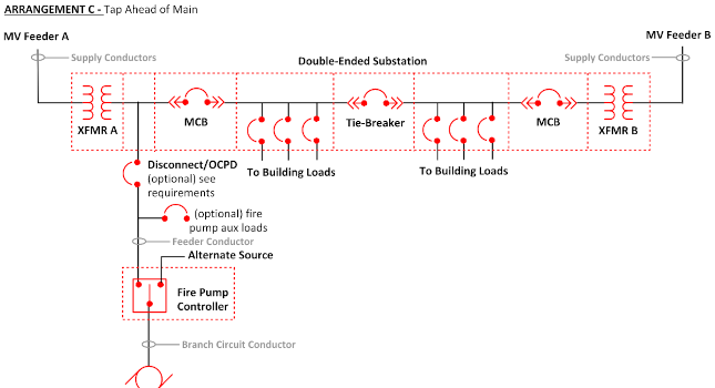
Per 695.3(A)(1), “a fire pump shall be permitted to be supplied by a separate service…” This could be a service lateral directly from a utility transformer to the controller. The other option mentioned is a connection from a shared utility service but connected ahead of any disconnecting means. It also mentions that this dedicated fire pump disconnecting means shall not share an enclosure, switchgear or switchboard section with any service disconnecting means.
There are 2 options we have available to meet this: The first is provide a dedicated service connection from the utility transformer to the fire pump controller. Therefore, the other is to provide a tap within the service switchboard/switchgear ahead of any service disconnecting mains. The Tap method would require a separate service switch for the fire pump. For instance, it can take the form of a fused disconnect switch, enclosed circuit breaker, or be integral to the service-rated fire pump controller.
695.3(B) Multiple Sources: If reliable power cannot be obtained from one of the sources mentioned in 695.3(A)(1) above, power shall be supplied by one of the following:
- 695.3(B)(1) Individual sources: any combination of two or more sources from 695.3(A)(1).
- 695.3(B)(2) Individual sources and on-site generator: any combination of one or more sources from 695.3(A)(1) and an On-site standby generator.
There is an exception to 695.3(B): If you install an engine-driven fire pump (Diesel) or a steam-powered turbine-driven fire pump, these exceptions eliminate the need for an alternate power source.
695.3(D) On-site Standby Generator as an Alternate Source: The standby generator must be sized to have sufficient capacity to allow normal starting and running of the fire pump, while supplying all other loads connected to the generator simultaneously. Thus, you can perform load shedding of optional standby loads to increase capacity on the generator if need be. Load shedding is a technique that allows the generator controller to shed or disconnect the load from the generator during certain times to gain extra capacity.
Now that we’ve discussed the code requirements for power sources, let’s explore how to maintain power continuity to keep the fire pump operational when it needs to perform its function.
Continuity of power
695.4 covers all the requirements for connecting fire pumps to the power source, as well as the permitted disconnecting means. Therefore, the goal of 695.4 is to prevent inadvertent disconnection of the fire pump from a power source. Disconnecting a fire pump from a source could result in loss of life so it is important that we maintain continuity of power so it fulfills it’s purpose. As mentioned earlier, designers set up fire pumps to run indefinitely, meaning they will run until they fail.

695.4(A) allows the supply conductors to directly connect the power source to a listed fire pump controller or transfer switch. When the transfer switch and/or controller has a service rating with an integral service switch, you can directly connect it to the utility power source without any additional disconnecting means.
If using the fire pump controller/transfer switch as the service disconnecting means and overcurrent protection it must meet 695.4(B)(2)(A)(2) which states the following:
- Overcurrent protection device shall not open within 2 minutes at 600% of full load current.
- Overcurrent protection device shall not open within a re-start transient of 24 times the full-load current.
- Overcurrent protection device shall not open within 10 minutes at 300% of full-load current.
- The trip point for circuit breakers shall not be field adjustable.
If we have an application where we cannot go directly from the utility transformer and need a tap within the service switchboard, we can use a single service disconnecting means with overcurrent protection. By 695.4(B)(1) between the power source and the following:
- A listed fire pump Controller
- A listed fire pump power transfer switch
- A listed combination fire pump controller and transfer switch
695.4(B)(2)(a)(1) describes the overcurrent protection requirements for the fire pump utility connection. The overcurrent protection device must be sized to carry the locked-rotor current of the largest fire pump motor and the full load current of all other loads being served. Locked Rotor current can be found by using Table 430.251(A). One trick that also works is to multiply the Full-Load current of the motor by 450%. This will get very close to the LRC.
695.4(B)(3) covers all the requirements for disconnecting means between the fire pump utility connection and the fire pump controller and/or transfer switch. Those requirements are:
Overcurrent protection requirements for the fire pump utility connection. We must size the overcurrent protection device to:
- Be identified as suitable for use as service equipment.
- Be lockable in the closed position.
- Not be located within the same equipment (switchboards/panelboard/cabinets etc) as other loads.
- Be located remote from other building service(s) and other fire pump disconnecting means.
- This disconnecting means must be marked “fire pump disconnecting means”.
For On-Site generator disconnecting means 695.4(B)(3)(c) points us to 700.10(B)(5). You can install the on-site generator disconnecting means (usually a generator-mounted circuit breaker). You can permit this installation in equipment that supplies other loads. But it must meet certain criteria in 700.10(B)(5). For single-generator applications, the most common way to achieve this is to provide a dedicated circuit breaker mounted on the generator output bus. We use this circuit breaker to feed the fire pump directly.
What about instances where we have multiple generators with paralleling switchgear? When using paralleling switchgear, 700.10(B)(5) permits the fire pump circuit breaker to share a common bus with non-emergency loads. As long as it is in a separate vertical section of switchboard or switchgear. An interesting point here is the word EMERGENCY. We consider the fire pump an emergency load, not a standby load. Hence, you can group it with other emergency load breakers in the same section.
695.4(B)(2)(b): Overcurrent protection devices between on-site standby generators and fire pump controller/transfer switch shall be sized to pick up full pump load and comply with 430.62. We size the fire pump OCPD on the generator as we would for any other motor using Table 430.52. You must size the overcurrent protection device to handle up to 250% of the motor’s full-load current.
Conductor Requirements
You must physically route service conductors and conductors from on-site generator(s) serving fire pumps on the outside of the building (659.6(A)(1)). However, if you cannot run conductors outside the building, you need to encase the conductors with 2 inches of concrete as per 230.6.

Source – https://engineercalcs.com/
Feeders from the load side of the disconnecting means (Service and On-Site generator) to the fire pump shall meet all the following requirements as per 695.6(A)(2):
- Conductors kept independent all of other wiring (No sharing pull boxes)
- Conductors shall supply only loads associated with the fire pump system.
- Conductors shall be protected from damage by fire structural failure or operational accident (routing them outside the building)
- Where routed inside the building conductors need to be 2-hour fire rated. There are 3 methods for this:
- 2 inches of concrete encasement of feeders
- fire-resistive cable system (such as mineral insulated cable)
- UL recognized 2-hour rated MC cable (Vitalink)
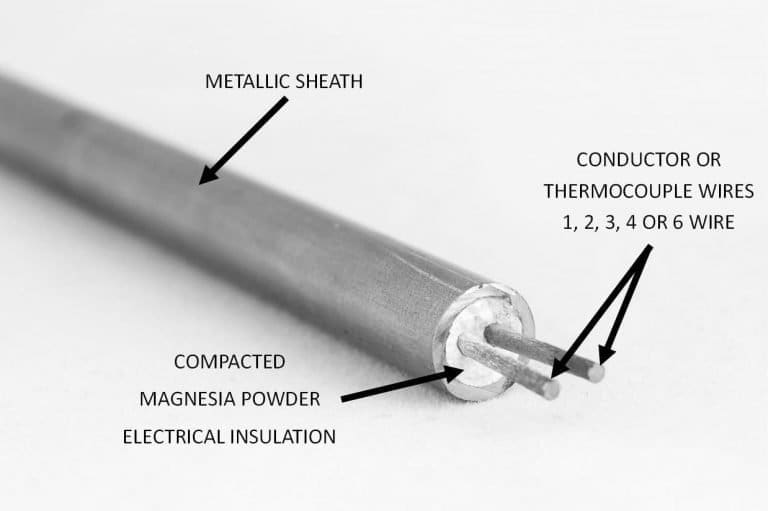
Source – https://zwcables.com/mi-cable/
Fire pump conductors supplying fire pump motor(s) and other loads shall have a rating of 125% of the sum of the fire Match OCDP type (fuse or Circuit breaker) listed on the nameplate of the equipment.
Conclusion
The installation and functioning of fire pumps form a cornerstone in the larger picture of building safety and fire protection. Not only do they sustain the necessary pressure in sprinkler systems, making them ready to spring into action when called upon, but they embody a complex yet finely orchestrated system guided by detailed norms set in place by NEC Article 695. From understanding the crucial role played by power sources and their continuity to appreciating the deep dive into intricate details around overcurrent protection and conductor requisites. Therefore, it is clear that equipping oneself with the knowledge of these guidelines isn’t just a regulatory mandate. But it’s also a critical step towards ensuring safety and functionality in fire protection systems.
All references to the National Electrical Code, NEC, or NFPA are copyrights of the NFPA, these citations are owned by the National Fire Protection Agency and are only here for educational reference.